BladeMesher Components
The following sections describe the components used to generate the blade mesh.
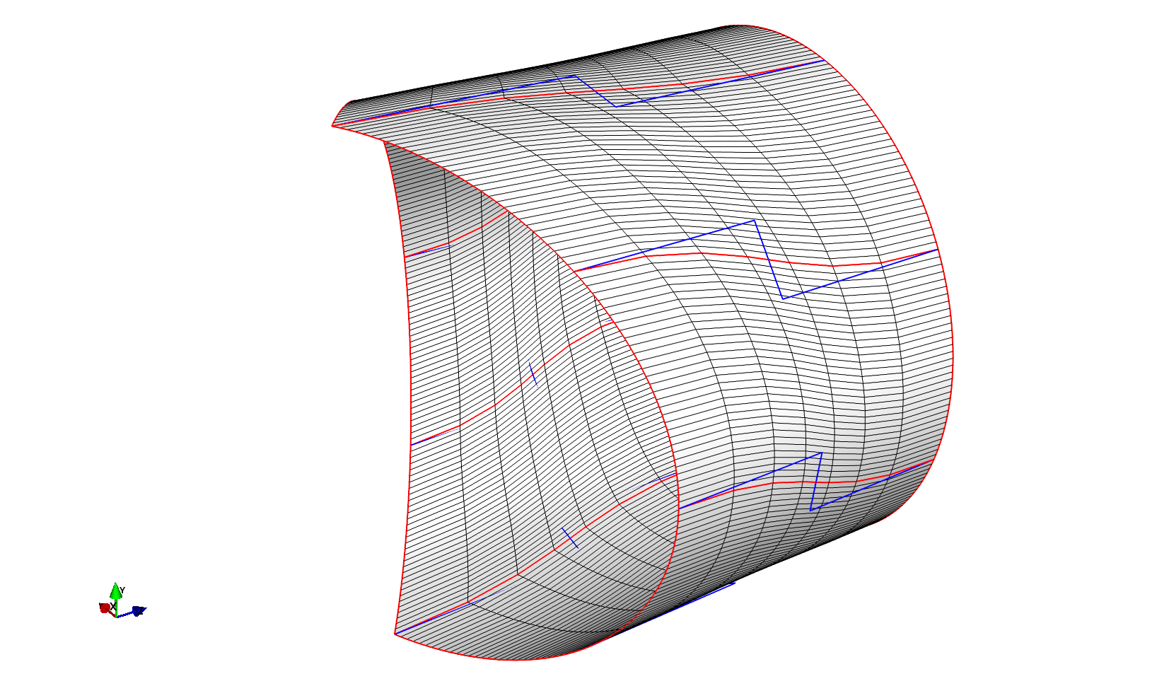
CoonsBladeRoot
The PGL.components.bladeroot.CoonsBladeRoot class generates a cylindrical surface where one end can be joined to form a 2, 3, or four-bladed rotors.
Generating a blade root is simple, requiring only the curve connecting to the main blade section:
from builtins import range
import numpy as np

from PGL.main.curve import Curve
from PGL.main.bladeroot import CoonsBladeRoot

# this curve will genererally be extracted from the main blade section surface
# but in this example we generate it manually
root_radius = 0.03
ni = 257
tip_con = np.zeros([ni, 3])
tip_con[:, 2] = 0.05
for i in range(257):
    tip_con[i, 0] = -root_radius * np.cos(360.*i/(ni-1)*np.pi/180.)
    tip_con[i, 1] = -root_radius * np.sin(360.*i/(ni-1)*np.pi/180.)

tip_con = Curve(tip_con)
tip_con.rotate_z(14.5)

root = CoonsBladeRoot()
root.tip_con = tip_con.points
root.nblades = 3                # Number of blades
root.ds_root_start = 0.006      # spanwise distribution at root start
root.ds_root_end = 0.003        # spanwise distribution at root end
root.s_root_start = 0.0         # spanwise position of root start
root.s_root_end = 0.05          # spanwise position of root end
root.ni_root = 8                # number of spanwise points
root.root_diameter = 0.06

root.update()
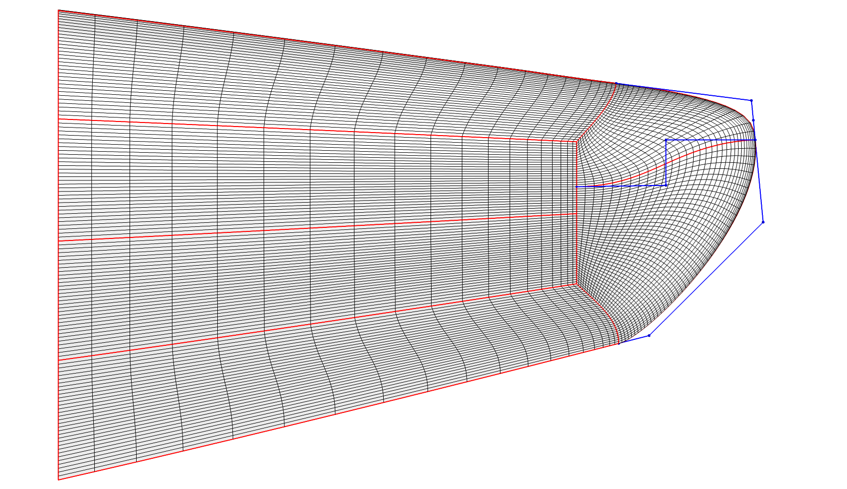
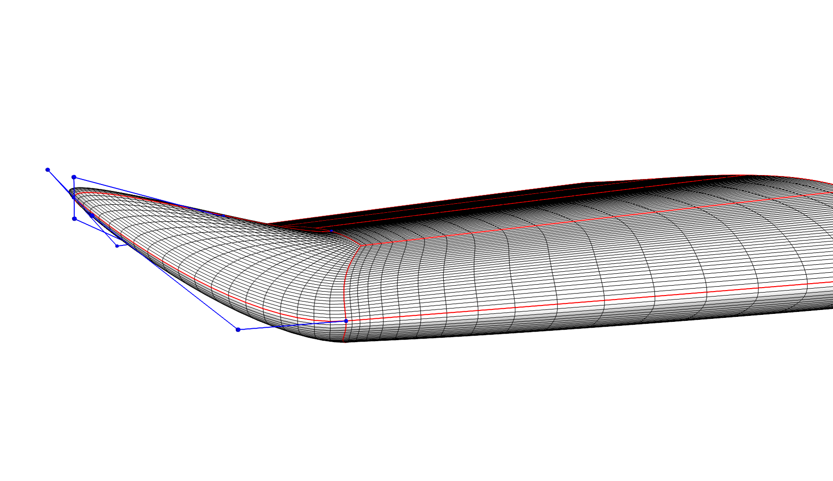
CoonsBladeTip
The PGL.components.bladetip.CoonsBladeTip class generates a blade tip surface mesh directly useable in a CFD rotor surface mesh.
Generating a blade tip requires a few more inputs than the root, since we can control the shape of the tip using a number of blending factors that control the tip thickness and planform. To ensure a smooth transition from the main blade section to the tip, the main surface is also a needed input.
Extending the CoonsBlade example script we add the blade tip:
tip = CoonsBladeTip()

tip.main_section = bl.domain.blocks['main_section']._block2arr()[:,:,0,:]

tip.fLE1 = .5  # Leading edge connector control in spanwise direction.
           # 'pointy tip 0 <= fLE1 => 1 square tip.
tip.fLE2 = .5  # Leading edge connector control in chordwise direction.
           # 'pointy tip 0 <= fLE1 => 1 square tip.
tip.fTE1 = .5  # Trailing edge connector control in spanwise direction.
           # 'pointy tip 0 <= fLE1 => 1 square tip.
tip.fTE2 = .5  # Trailing edge connector control in chordwise direction.
           # 'pointy tip 0 <= fLE1 => 1 square tip.
tip.fM1 = 1.  # Control of connector from mid-surface to tip.
          # 'straight line 0 <= fM1 => orthogonal to starting point.
tip.fM2 = 1.  # Control of connector from mid-surface to tip.
          # 'straight line 0 <= fM2 => orthogonal to end point.
tip.fM3 = .3  # Controls thickness of tip.
          # 'Zero thickness 0 <= fM3 => 1 same thick as tip airfoil.

tip.dist_cLE = 0.0001  # Cell size at tip leading edge starting point.
tip.dist_cTE = 0.0001  # Cell size at tip trailing edge starting point.
tip.dist_tip = 0.00025  # Cell size of LE and TE connectors at tip.
tip.dist_mid0 = 0.00025  # Cell size of mid chord connector start.
tip.dist_mid1 = 0.00004  # Cell size of mid chord connector at tip.

tip.s_tip = 0.995  # Cell size at tip mid chord connector end.
tip.s_tip_start = 0.98  # Cell size at tip mid chord connector end.
tip.c0_angle = 30.  # Angle of connector from mid chord to LE/TE
tip.ds_tip_start = 0.001 # Cell size in spanwise direction at tip domain start

tip.ni_tip = 20  # Index along main axis where the tip domains replace the blade_section
tip.nj_LE = 20   # Index along mid-airfoil connector used as starting point for tip connector

tip.Ptip = np.array([0.0, 0.0, 1.])

tip.update()
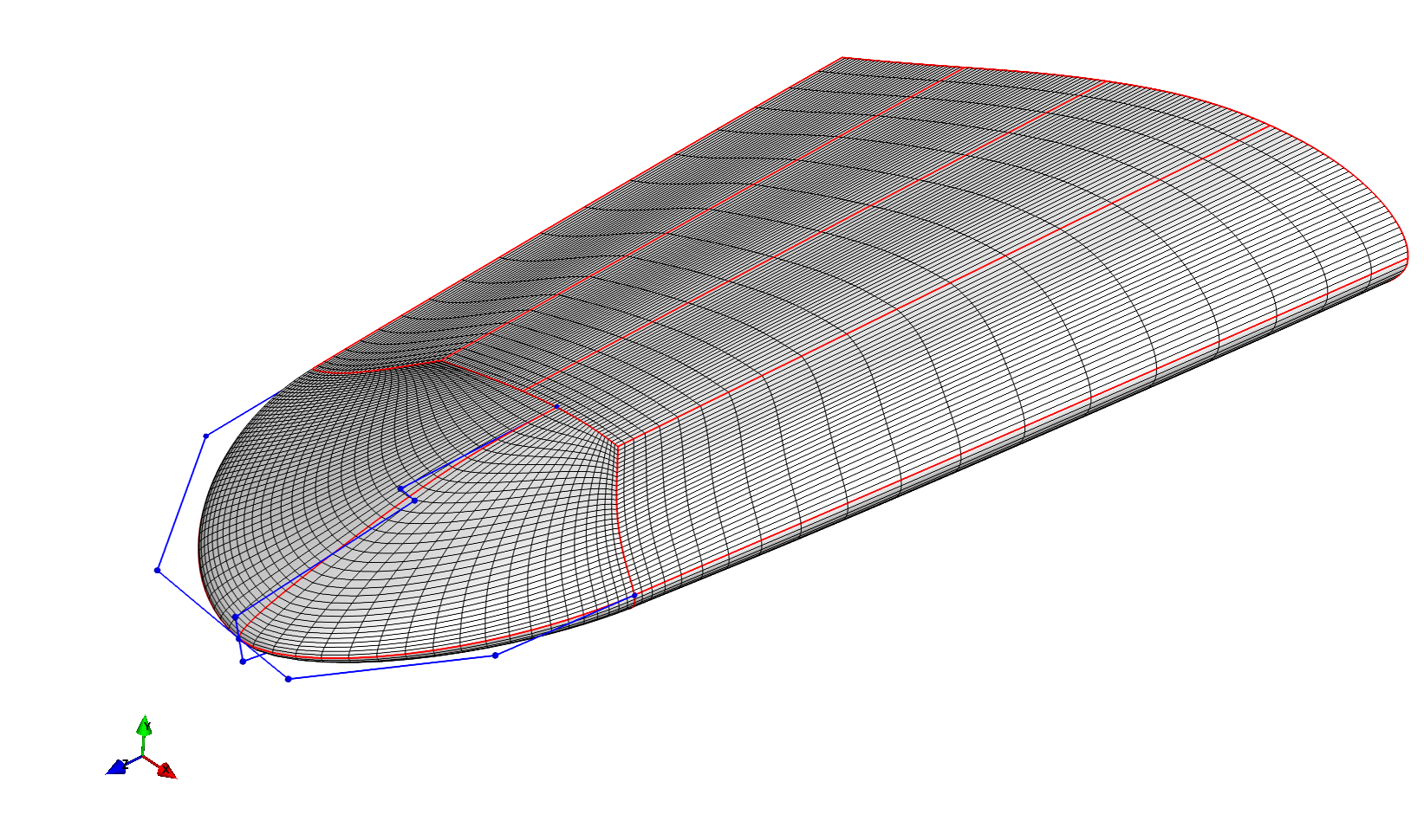
Changing the control parameters and position of the tip point can alter the shape of the tip considerably.
You can to a modest extent also place the tip point out of the y-plane, however, it is recommended to instead introduce winglet-like shapes into the main blade section, and simply fit the tip component to this.
LoftedBladeSurface
The PGL.components.loftedblade.LoftedBladeSurface class builds a blade surface based on a planform definition and an airfoil family.
The example in examples/loftedblade_example.py shows the basic usage of this class:
import numpy as np

from PGL.main.loftedblade import LoftedBladeSurface
from PGL.main.planform import read_blade_planform, redistribute_planform

pf = read_blade_planform('data/DTU_10MW_RWT_blade_axis_prebend.dat')

dist = [[0, 0.01, 1],
        [0.05, 0.01, 8],
        [0.98, 0.001, 119],
        [1., 0.0005, 140]]

pf = redistribute_planform(pf, dist=dist)

d = LoftedBladeSurface()
d.pf = pf
d.redistribute_flag = True
# d.minTE = 0.0002

d.blend_var = [0.241, 0.301, 0.36, 1.0]
for f in ['data/ffaw3241.dat',
          'data/ffaw3301.dat',
          'data/ffaw3360.dat',
          'data/cylinder.dat']:

    d.base_airfoils.append(np.loadtxt(f))

d.update()
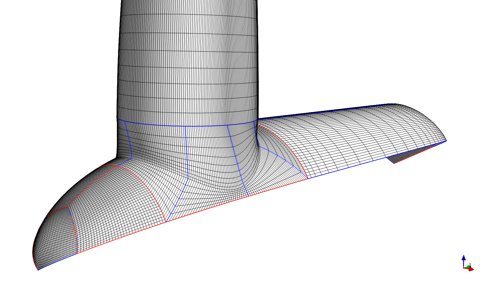
CoonsNacelle
The PGL.components.nacelle.CoonsNacelle class builds a rotationally symmetric spinner and nacelle surface that attaches to the blade root, replacing the simpler CoonsBladeRoot.
CoonsBlade
The PGL.components.coonsblade.CoonsBlade class uses the PGL.main.extruded_section.ExtrudedSection to generate a full blade surface.
In the example shown below we also use the PGL.components.airfoil.BlendAirfoilShapes to create interpolated airfoil cross-sections along the blade.
import numpy as np

from PGL.main.curve import Curve
from PGL.main.coonsblade import CoonsBlade
from PGL.main.airfoil import AirfoilShape, BlendAirfoilShapes

# make an airfoil interpolator to reproduce the DTU 10MW RWT
interpolator = BlendAirfoilShapes()
interpolator.ni = 257
interpolator.spline = 'pchip'
interpolator.blend_var = [0.241, 0.301, 0.36, 1.0]
for f in ['data/ffaw3241.dat',
          'data/ffaw3301.dat',
          'data/ffaw3360.dat',
          'data/cylinder.dat']:

    interpolator.airfoil_list.append(np.loadtxt(f))
interpolator.initialize()

pf = np.loadtxt('data/DTU_10MW_RWT_blade_axis_prebend.dat')

s = [0., 0.05, 0.2, 0.3, 0.4, 0.6, 0.8,0.97, 1.]
rthick = np.interp(s, pf[:,2]/86.366, pf[:,7]/100.)
chord = np.interp(s, pf[:,2]/86.366, pf[:,6]/100.)
twist = np.interp(s, pf[:,2]/86.366, pf[:,5])
p_le = np.interp(s, pf[:,2]/86.366, pf[:,8])

# chord[[0, 1]] = 4.5/86.366
# chord[-1] = 0.001

bl = CoonsBlade()

bl.np = 4
bl.chord_ni = 257

dp = ['z', 'z', -1, -1, -1, -1, -1, -1, -1]
fWs = [0.5] * 9
fWs[-2] = 0.25
fWs[-1] = 0.01

for i, s in enumerate(s):
    bl.add_cross_section(interpolator(rthick[i]), pos=np.array([0, 0, s]),
                                     rot=np.array([0, 0, twist[i]]),
                                     chord=chord[i],
                                     p_le=p_le[i],
                                     dp=dp[i], fWs=fWs[i])


bl.update()
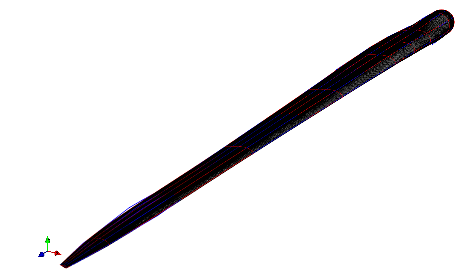
As you can see the blade is generated by adding a number of cross-sections along the span, with a given chord, rotation and so-called pitch axis aft leading edge.
The two additional parameters dp and fWs control the gradient of the span-wise edge curves at the sections, and the distance of the Bezier control points from the sections.
Running the example should generate a surface that looks like this: